

How to set up V9 V1.2 test jig manual for S9 series, S11, S15, T15, DR5, D5, S17, S17PRO and T17
Автор публикации: Bit2minerSupport, дата:
V9 V1.2 hashboard tester is applicable to S9 series, S11, S15, T15, DR5, D5, S17, S17PRO, and T17.
I. Preparatory work
- Platform: computer (Win10 system)
- Tools: electric soldering iron (60W), solder wire
- Tester: hashboard tester V1.2 (buy from Bitmain official website)
- Drop-out line: 1 S9 drop-out line (buy 1 tester, get 1 drop-out line for free)
- Voltage regulating line: voltage regulating line is comparatively short, but can be extended (DIY), such as using abandoned fan line.
- Fan: 4 fans are needed when testing S17, S17PRO and T17. Tester has only two fan interfaces. Buy one-to-two connectors for fan or use other power supplies to let the 4 fans meet the need of heat dissipation. Up and down cooling or side cooling are needed. (buy from official website)
- Power source: suggest 12V power source APW3, APW8 and APW9 for direct power supply according to testing model, to avoid the tester blackout caused by overcurrent when tested by 12V adapter.
- TF card: burn test program as needed. Note: for S15, T15, S17, S17PRO, T17, DR5 and D5, master program of corresponding model needs to be copied to tester before normal testing.
- USB to serial interface: for CP210X series or TL43X series, search keywords “USB to TTL” in Taobao to get.
- Dupont line: male and female 3P >30cm, generally the Dupont line of serial interface is OK.
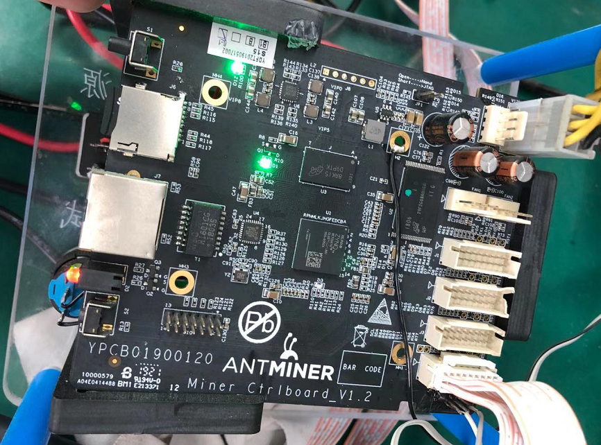
II. Hardware connection
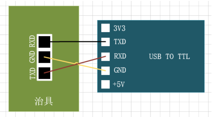
- First, connect serial interface. Connect control panel and serial interface board as shown in the fig:
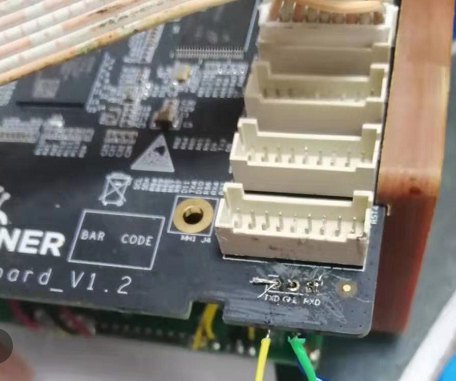
- Weld serial interface board, and connect drop-out line.
- Connect voltage regulating line, and pay attention not to plug in the position of two side-by-side fans.
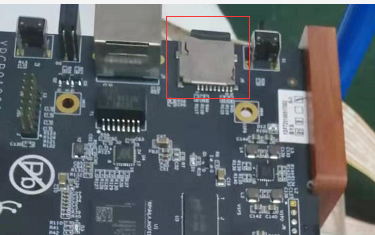
- Copy the master program that testing model needs.
- Insert the prepared SD card of the corresponding model.
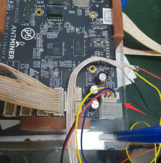
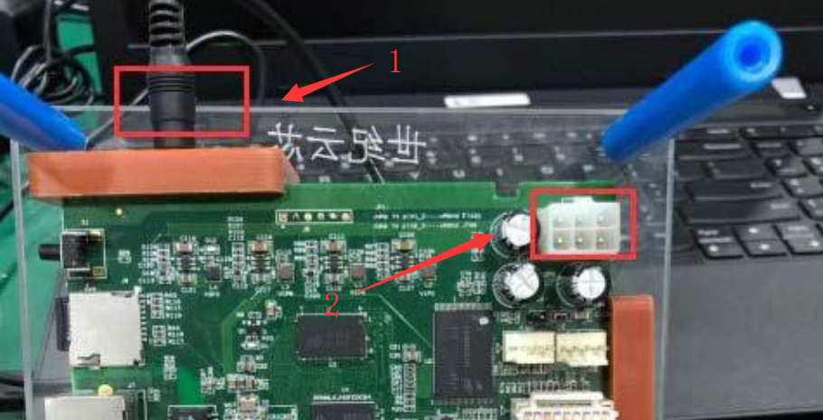
- Plug power in. The interface in below fig 1 is an adapter power interface, and it is ok to directly insert to the power interface. APW3 power should insert to the 6PIN interface of the control panel 2, but in that case, the power switch of tester will not work.
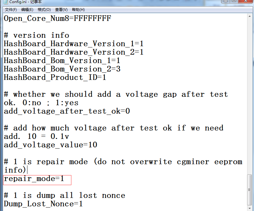
- Configuration file description: repair=0, test will overwrite eeprom, and whole machine needs frequency sweep again; repair=1, test will not overwrite eeprom, and whole machine test and hash rate will not be affected.
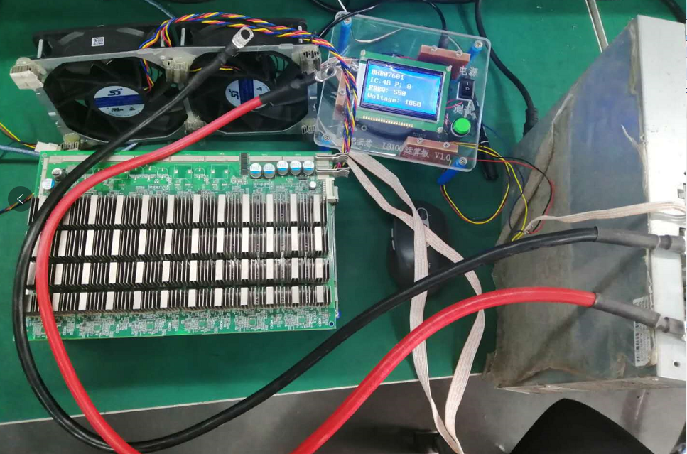
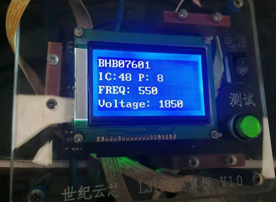
- Start interface (For instance, S17 and S17pro have the same interface, so does single board testing program)
III. Notes
- After the chip is tested when testing S17, S17PRO and T17, the temperature rises quickly, and 4 fans are a must for cooling. (Refer to the picture when making. Note: during the test, must not let hashboard touch any metal object, to avoid short circuit).
If 4 fans cannot be all inserted to the tester of control panel, pull out the blue line, to let fans reach full speed, or the board or chip might be burnt; besides, the cooling fins on front and back sides of the board are all electrified, so must not let any metal object touch hashboard, or chip might be damaged or board might be burnt; all test results should be OK, or the frequency sweep of whole machine test will be NG;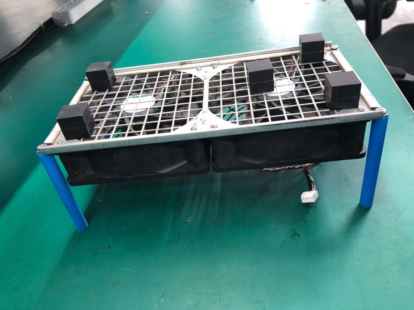
- Voltage regulating line needs to be connected to test power source. Do not randomly connect when making extension line. If unclear, remove one line and connect one line, to avoid errors;
- Copy the corresponding master program of tester when testing different models (except S9, S9i, S9j, and T9+ which can use general packet, all other models need copy);
- Tester and hashboard should use separate powers, or the tester is easy to be burnt; if use 12V adapter, 12V 5A and above should be guaranteed.
- When using V9 V1.2 version tester, the line losses of test power line should be less than 0.1V (below 100mV). For instance, if power outputs 18.5V, the voltage at the power interface of hashboard should not be less than 18.4V. When the line losses of power are bigger than 0.1V, it is more easily to cause single board PATTER NG;
- For S9K and S9SE, corresponding config and single-board-test files need to be configured;
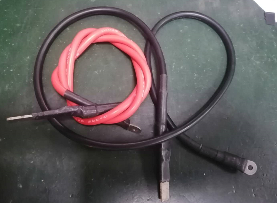
- Customers need to make copper axis themselves to connect hashboard (at least 6 square flexible cord), one end has a screw hole to connect APW8 or APW9, and the other end needs to be stuck on hashboard (both joints need to be isolated by heat-shrinkable sleeves, as shown below)
Source:https://support.bitmain.com/hc/en-us/articles/360039323873-How-to-set-up-V9-V1-2-test-jig-manual-for-S9-series-S11-S15-T15-DR5-D5-S17-S17PRO-and-T17
Поделиться записью
← Более старые записи Более новые записи →